42 electric motor diagram with labels
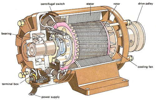
The picture shows a basic diagram of an electric motor. Which labels ... The picture shows a basic diagram of an electric motor. Which labels best complete the diagram? X: Brush Y: Armature Z: Commutator X: Commutator Y: Brush Z: Armature X: Armature Y: Commutator Z: Brush X: Armature Y: Brush Z: Commutator Expert-verified answer SerenaBochenek OMTEX CLASSES: Explain the construction and working of the following ... Draw a neat diagram and label it. Electric motor Answer: Electric motor - It converts electrical energy into mechanical energy. Principle- When a current carrying conductor is placed normally in a magnetic field it experiences a force which rotates the conductor thus mechanical energy is generated. Construction-
wiring an electric motor diagram Motor wiring phase single switch 230v drum ge help electrical wires terminal 5hp any circuit. Motor diagram wiring weg connection voltage iec 480v low 10hp. Rewire a 10hp weg motor (low and high voltage) wiring an electric motor diagram. Reversing single phase induction motors we have 9 Pictures about Reversing single phase induction motors ...

Electric motor diagram with labels
Draw a labelled diagram of an electric motor ... - Sarthaks eConnect Working of Electric Motor Current in the coil ABCD enters from the source battery through conducting brush X and flows back to the battery through brush Y. The current in arm AB of the coil flows from A to B. In arm CD it flows from C to D, that is, opposite to the direction of current through arm AB. PDF Understanding Electric Motor Nameplates In Table 1, there is a column labeled shaft diameter. Figure 2 This is a bottom view of an electric motor showing the mounting bracket and ... VOLTS Electric motors must be matched to the voltage of the circuit. Some motors are only single voltage. If that is the case, then only one voltage will be shown on the nameplate. ... Electric motor Diagram | Quizlet The commutator is a broad ring of metal mounted on the axle at one end of the armature, and cut into an even number of separate bars (2 in a simple motor). Each opposite pairs of bars is connected to one set of coils.
Electric motor diagram with labels. Electric Motor Symbols Electric motors are electromechanical devices whose function is to transform electrical energy into mechanical energy through electromagnetic interactions. There are other engines ( generators) that produce electricity by exploiting the mechanical energy, such as alternators and dynamos. It may interest you... General Electric Motor Wiring Diagram - Database The white wire is the neutral wire and switches into the neutral airport terminal, which is marked by silver/light-colored anchoring screws. The black line, on the other hand, is the hot wire and goes into the hot terminal, the one opposite the neutral terminal. Draw a labelled diagram of an electric motor, principle and worki No 11: Draw a labelled diagram of an electric motor. Explain its principle and working. What is the function of a split ring in an electric motor? Ans: An electric motor is a device which converts electrical energy into mechanical energy. The principle behind the electric motor is based on Fleming's left hand rule. Electrical Symbols, Electrical Diagram Symbols - ConceptDraw Electrical rotating machines, such as motors and generators, are vital assets for any power plant or large industrial company. An electric motor is an electrical machine that converts electrical energy into mechanical energy. The reverse of this would be the conversion of mechanical energy into electrical energy and is done by an electric generator. In normal motoring mode, most ...
Question 11 Draw a labelled diagram of an electric motor ... - Byju's Principle: It works on the principle of the magnetic effect of current. A current-carrying coil rotates in a magnetic field. Working: When a current is allowed to flow through the coil MNST by closing the switch, the coil starts rotating anti-clockwise. This happens because a downward force acts on length MN and at the same time, an upward force acts on length ST. Draw a labelled circuit diagram of a simple electric motor and explain ... A commercial electric motor is one which uses the following (i) An electromagnet in place of permanent magnet. (ii) Large number of turns conducting wire in current carrying coil. (iii) A soft iron core on which the coil is wound. The combination of soft iron core and coil is an armature. It enhances the power of motor. 7 Parts Of Simple Electric Motor And Function - AutoExpose The trunk, the magnet is placed on a pivot with the circuit in such a way that it can produce rotary motion when these two components interact. Electric Motor main Components 1. Stator Coil 2. Rotor Coil 3. Main Shaft 4. Brush 5. Bearing 6. Drive Pulley 7. Motor Housing Simple Motor Parts and their function 1. Stator / Armature Coil labeled diagram simple electric motor Electromagnet diagram draw physics labelled electromagnets magnet iron magnetic construction igcse field switch relay describe neat solenoid poles core coil. Motor control circuit diagram / start stop 3 wire control. Generator dc construction parts field magnetic main system diagram pole armature machine circuit globe commutator electrical ...
Electric Motor Diagrams - Mr. Electrician's Home Page A Split Phase Capacitor Start Electric Motor may be defined as a form of split-phase motor having a capacitor connected in series with the auxiliary winding. The auxiliary circuit is opened by the centrifugal switch when the motor reaches 70 to 80 percent of synchronous speed. Also known as a capacitor-start, induction-run motor. Dc Motor Wiring Diagram - Database - Wiring Diagram Sample Dc Motor Wiring Diagram Source: img.favpng.com. Read electrical wiring diagrams from unfavorable to positive and redraw the signal being a straight collection. All circuits are usually the same : voltage, ground, individual component, and switches. Dc Motor Wiring Diagram Source: . Dc Motor Wiring Diagram Source: i.ytimg.com. Three Phase Motor Power & Control Wiring Diagrams Three Phase Motor Connection STAR/DELTA Without Timer - Power & Control Diagrams. Three Phase Motor Connection Star/Delta (Y-Δ) Reverse / Forward with - Timer Power & Control Diagram. Starting & Stopping of 3-Phase Motor from more than One Place Power & Control diagrams. Control 3-Phase Motor from more than Two buttons - Power & Control ... Types of electric vehicles with labeled battery and motor outline diagram Types of electric vehicles with labeled battery and motor outline diagram. Illustration about comparison, auto, chassis, outline, isolated, technology, fossil, diagram - 217894989 ... Types of electric vehicles with labeled battery and motor outline diagram. Educational scheme with hybrid, plug-in and electricity car power supply vector ...
How do electric motors work? - Explain that Stuff
What is an Electric Motor? with the Help of a Labelled Diagram ... An electric motor is a device that converts electrical energy into mechanical energy. Diagram: Electric motor Working of an electric motor: An electric motor works on the principle of magnetic effect of electric current.

Patent US7116018 - Electric motor - Google Patents
Draw a labeled diagram of an electric motor. Explain its principle and ... Working of electric motor: As shown in the diagram, when a current is passed through the coil PQRS the coil starts rotating anti clockwise because a downward force acts on length PQ and at the same time an upward force acts on RS. Therefore, the coil rotates in anti clockwise direction.

Simple Electric Motor Diagram Class 10 See More on | Home Lifestyle Design Simple
Electrical Diagrams and Schematics - Inst Tools Types of Electrical Diagrams or Schematics. There are three ways to show electrical circuits. They are wiring, schematic, and pictorial diagrams. The two most commonly used are the wiring diagram and the schematic diagram. The uses of these two types of diagrams are compared in Table 1. The pictorial diagram is usually not found in engineering ...
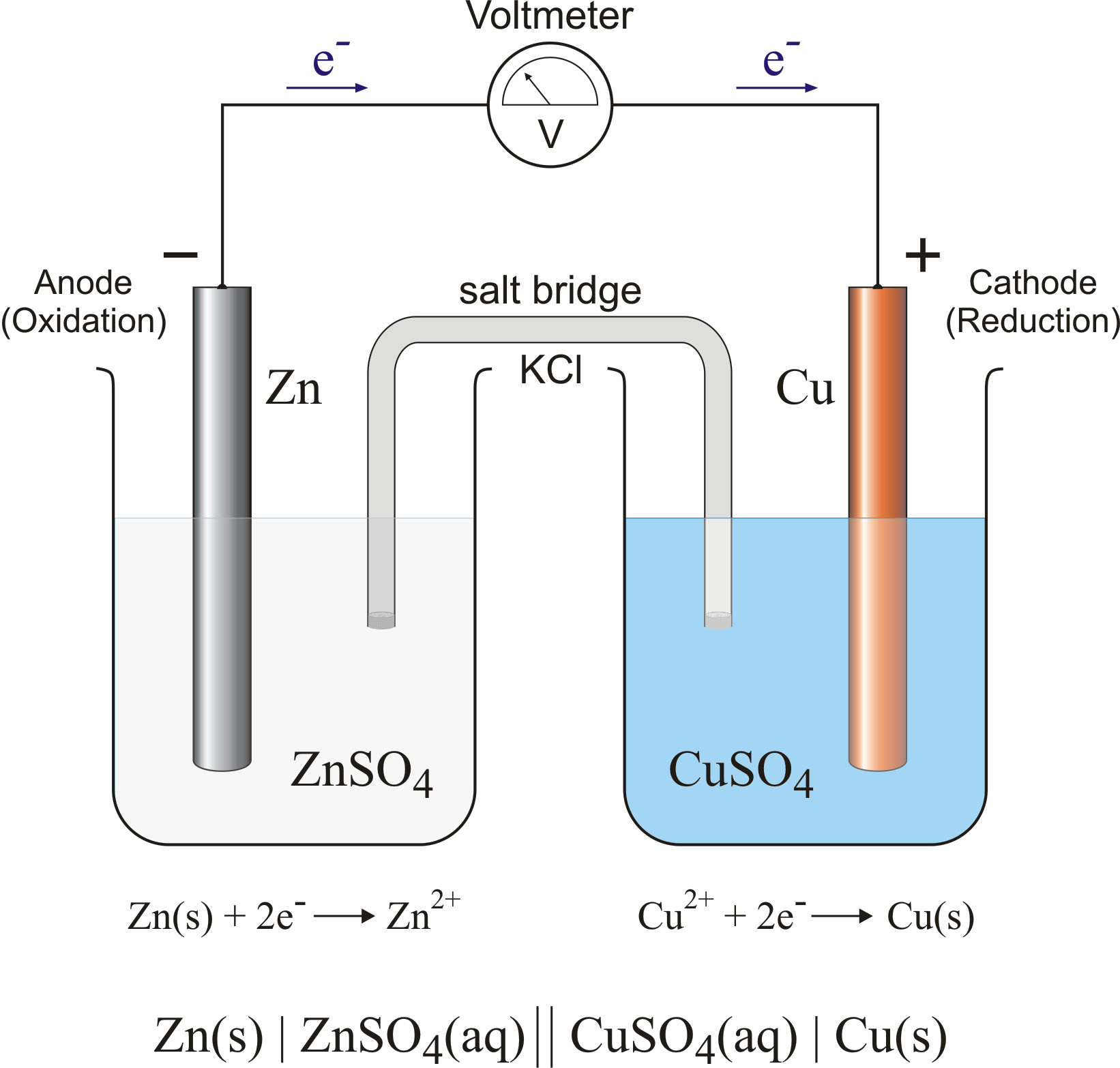
Electrochemical cell @ Chemistry Dictionary & Glossary
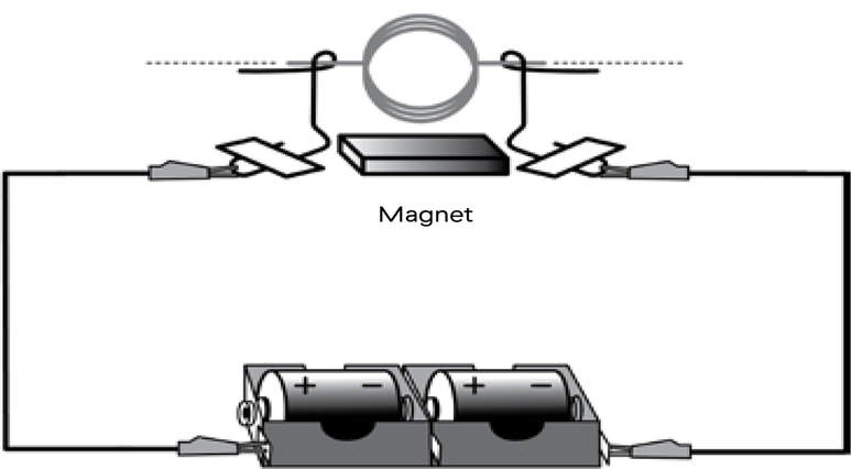
Parts of Motor, Working of Electric Motor & Uses - BYJUS Take two bar magnets and keep the poles facing each other with a small space in between. Now, take a small length of a conducting wire and make a loop. Keep this loop in between the space between the magnets such that it is still within the sphere of influence of the magnets. Now for the last bit. Connect the ends of the loop to battery terminals.

Electrical Engineering World: Power & Control Circuit for Forward and Reverse Motor
Electric Car Diagram - Car Construction Car Anatomy and Repair, Electric car, Engine, How a car Works, Construction. The active reference to source is obligatory if you use materials of a site Car Anatomy 889 shares

Honda WP30X ACF6/A WATER PUMP, JPN, VIN# WZBF-1300001 Parts Diagram for CASING + IMPELLER
Motor Connection Diagrams - Electric Motor Warehouse Single Phase Terminal Markings Identified By Color: (NEMA Standards) 1-Blue 5-Black P1-No color assigned. 2-White 6-No color assigned P2-Brown. 3-Orange 7-No color assigned. 4-Yellow 8-Red. Three Phase Connections: Part Winding Start: 6 Leads NEMA Nomenclature: WYE or Delta Connected.

Patent US6759773 - Electronically controlled electric motor provided for use in an environment ...
Electric Motors Symbols - AC/DC, Single Phase / Three Phase Motors This is the symbol of a generic electrical motor that is used in electrical schematics. A motor converts electrical energy into mechanical energy. Dual Speed Motor This symbol represents a dual speed motor. Such type of motors has two separate windings for different speed ratios. Each winding provide different speed & torque at a single time.

Electrical Engineering World: ِA Complete diagram of an off-grid solar power system
Single Phase Electric Motor Wiring Tutorial: Baldor, WEG, Leeson In this video, Jamie shows you how to read a wiring diagram and the basics of hooking up an electric air compressor motor. These tips can be used on most ele...
(EN) – Glossary of Electric Motor Terms | reliance.com – 📚 Glossarissimo!
Electric Motor Nameplate Details Explained | Electric Motor ... The nameplate shown in Figure 1 indicates the electric motor is rated 1 HP. With a service factor of 1.15, the motor can be overloaded up to 1.15 horsepower. If the motor is operated in the service factor range continuously, it will cause a reduction in motor speed and efficiency, and an increase in the motor's operating temperature.

Draw a labelled diagram of an electric motor. Explain its principle and working | NCERT ...
Electric Motor - Principle, Working, Diagram - teachoo Electric Motor consists of Rectangular Coil of Wire ABCD A strong horseshoe magnet (or 2 different magnets ) - If we take 2 magnets, North Pole of first magnet faces South Pole of Other Magnet, as shown in figure... The coil is placed perpendicular to the magnet as shown in figure The ends of coil are connected to split rings - P & Q

Basic #Electric #Motor #Components Join Our Blog: http://www.electricaltechnology.org ...
Electric motor Diagram | Quizlet The commutator is a broad ring of metal mounted on the axle at one end of the armature, and cut into an even number of separate bars (2 in a simple motor). Each opposite pairs of bars is connected to one set of coils.
Electric Motor
PDF Understanding Electric Motor Nameplates In Table 1, there is a column labeled shaft diameter. Figure 2 This is a bottom view of an electric motor showing the mounting bracket and ... VOLTS Electric motors must be matched to the voltage of the circuit. Some motors are only single voltage. If that is the case, then only one voltage will be shown on the nameplate. ...

Patent US6271609 - Programmable electric motor and method of assembly - Google Patents
Draw a labelled diagram of an electric motor ... - Sarthaks eConnect Working of Electric Motor Current in the coil ABCD enters from the source battery through conducting brush X and flows back to the battery through brush Y. The current in arm AB of the coil flows from A to B. In arm CD it flows from C to D, that is, opposite to the direction of current through arm AB.

Electrical Engineering World: Utility Pole Parts

Explain Electric Motor

Encounters In Mind: Notes - let them be / polite&honest / electric motor / sharable thought

Electrical Engineering World: AC Split-Phase Induction Motor
Post a Comment for "42 electric motor diagram with labels"